Rabu, 07 November 2012

metalografi


LAPORAN PRAKTIKUM
METALOGRAFI


oleh
RR Alvina Rana Prabowo
111221026
2 Aeronautika

POLITEKNIK NEGERI BANDUNG


Tujuan Praktikum
1.      Melakukan prosedur metalografi dengan benar
2.      Mengetahui struktur mikro material
Dasar Teori
Metalografi adalah salah satu cara untuk melakukan pemeriksaan struktur mikro pada logam dengan pengamatan dibawah mikroskop optic. Struktur mikro meliputi fasa yang setimbang. Fasa yang setimbang adalah fasa yang terbentuk dari fasa cair ke fasa padat dengan laju pendinginan sangat lambat. Jenis fasa ini terdiri dari perlit, ferit, austenite dll yang dapat dianalisis dengan menggunakan diagram fasa (Fe-C). Fasa yang tidak setimbang adalah fasa yang terbentuk akibat pendinginan cepat. Jenis fasa ini terdiri atas martensit, bainit, yang dapat dianalisis dengan menggunakan diagram CCT (Continous-Cooling Transformation). Sedangkan ditinjau dari bentuk butir logam memiliki dua bentuk butir, yaitu butir equaxial dan elongation.
Terdapat 2 skala pengamatan:
1.      Skala Pengamatan Makro: Pengamatan dengan perbesaran10X atau lebih kecil.
Yang diamati: Porositas, segregasi pad aprodukcor, pengotor, jenis perpatahan,homogenitas struktur las
2.      Skala pengamatan mikro: Pengamatan100x atau lebih besar.
Yang diamati: fasa, besar butir, endapan.
 Alat yang digunakan: MikroskopOptik(s/d 1000 x),Scanning Electron Microscope(SEM); (s/d 300000 x), Transmission Electron Microscope (TEM); (s/d 1000000 x)
            Diagram fasa Fe-C adalah diagram fasa biner besi-karbon dengan keluratan karbon didalam besi maksimum 6.7% . Analisis pada diagram fasa Fe-C dengan asumsi bahwa pendinginan dari fasa cair ke fasa padat dilakukan dengan laju pendinginan yang sangta lambat. Pada digram fasa tersebut terdapat tiga reaksi fasa yaitu reaksi fasa peritektik, eutektek, dan eutectoid. Sedangkan fasa yang terbentuk antara lain : austenite, feritik, perlitik, sementit. Apabila ditinjau dari % C pada Fe, diagram tersebut dikelompokkan ke dalam empat yaitu : baja hypoeutektoid, baja hypereutectoid, besi cor hypoeutektik dan besi cor hypereutektik. Bentuk diagram fasa Fe-C dapat dilihat pada Gambar 1-1
            Diagram fasa Continous Cooling Transformation (CCT) adalah diagram yang menggambarkan proses pendinginan dari fasa austenite ke fasa yang lain dilakukan dengan pendinginan yang beragam, termasuk media pendinginnya. Dengan laju pendinginan yang beragam tersebut, strukur mikro logam mengalami perubahan, yang berakibat pada perubahan sifat mekanik bahan utamanyaterhadap kekerasan. Namun demikian tidak semua baja dapat dikeraskan, tergantung pada kandungan karbon atau karbon ekivalennya.


Gambar 1-2 Struktur mikro baja sebagai fungsi pendinginan


Alat yang Digunakan
1.      Alat pemotong spesimen
2.      Alat monting
3.      Rotary grinding dan alat poles
4.      Alat pengering spesimen
5.      Mikroskop optik
Bahan yang Diperlukan
1.      Ampelas kasar sampai halus (100-200)
2.      Larutan etching
3.      Kapas
Langkah kerja
Sebelum praktikum
·         Lakukan penetapan atau pemilihan sampel logam yang akan diperiksa struktur mikronya
·         Lakukan studi literatur untuk mendeskripsikan spesimen yang akan diperiksa
·         Lakukan pemotongan spesimen sesuai dengan studi literatur
·         Lakukan mounting spesimen untuk memudahkan dalam pemegangan benda uji

Mempersiapkan spesimen metalografi
·         Lakukan penggerindaan spesimen yang sudah dimountingdengan menggunakan mesin rotary grinding. Gunakan ampelas dari yang terkasar (nomor terkecil) sampai yang terhalus (nomor terbesar)
·         Permukaan spesimen  diusahakan rata pada kedua bidangnya, agar pada saat pengamatan tidak terjadi bias
·         Bila penggerindraan atau pengampelasan telah selesai, lakukan pemolesan pada bagian permukaan yang akan dijadikan objek pengamatan
·         Gunakan mesin poles dan kain poles yang halus serta pasta peleshing yang ada
·         Pada saat melakukan pemolesan, usahakan permukaan benar-benar terbebas dari goresan bekas ampelas.Gunakan mikroskop untuk melihat ada atau tidaknya bekas goresan
·         Etching. Gunakan table etching yang ada
Problem etching
·         Struktur mikro tidak muncul, hal ini disebabkan oleh waktu etching yang kurang lama, atau pilihan larutan etching tidak sesuai dengan spesimen.


·         Struktur terkorosi atau over etching , hal ini disebabkan oleh waktu etching yang terlalu lama. Bila hal ini terjadi lakukan pemolesan kembali

Analisis

austenit
 
grafit


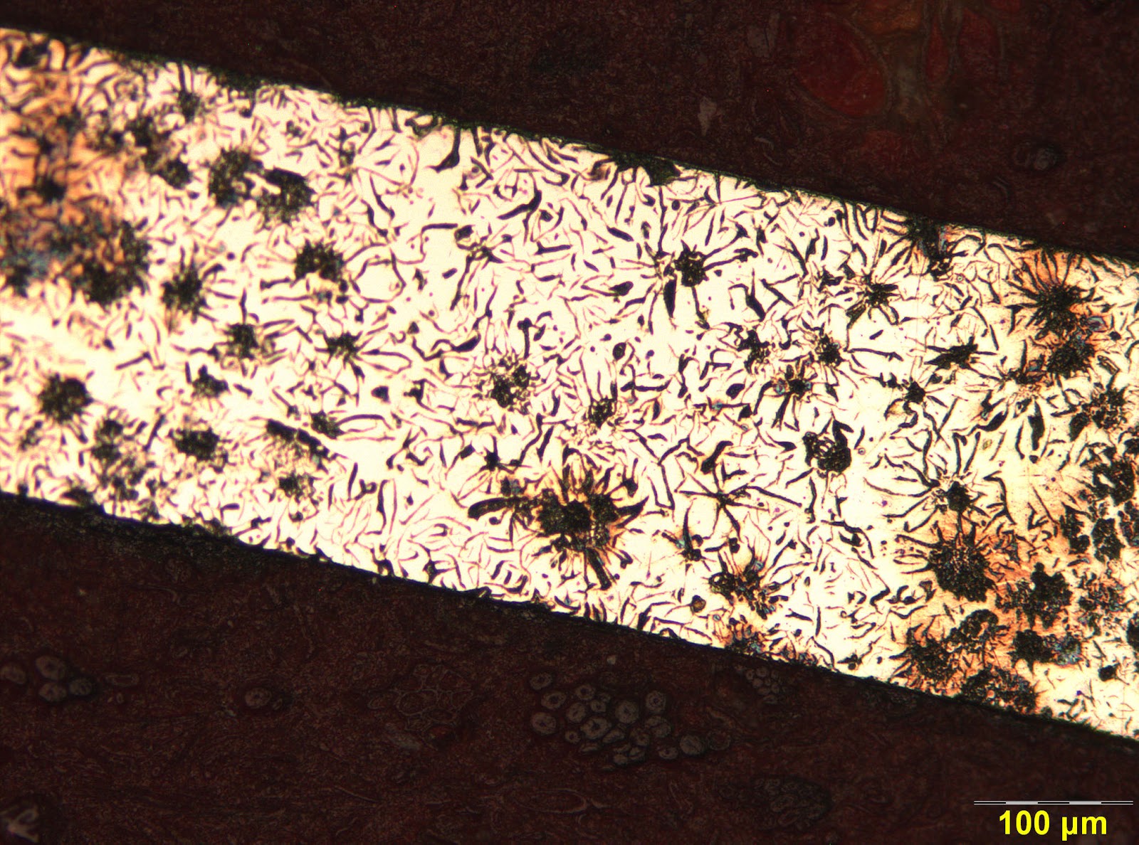
Dari hasil pengambilan gambar menggunakan mikroskop, maka didapatkan bahwa struktur mikro pada material tersebut adalah struktur mikro dari besi tuang atau besi cor, lebih tepatnya adalah besi cor kelabu, ditandai dengan adanya bentuk seperi cacing pada struktur mikro tersebut. Besi cor kelabu terbentuk ketika karbon dalam paduan berlebih hingga tidak larut dalam fasa austenitnya dan membentuk grafit berbentuk serpih (flake). Jika besi cor ini dipatahkan maka permukaan patahannya berwarna abu-abu sehingga disebut besi cor kelabu. Besi cor kelabu adalah salah satu material teknik yang penting karena memiliki banyak kegunaan, biaya produksinya relatif murah, mampu mesin yang sangat baik, tahan aus, dan memiliki efek peredam getaran(damping capacity). Secara umum besi cor kelabu memiliki kandungan karbon (2,5 – 3,5) %, silikon (1,5 – 3,0) %, mangan (0,5 – 0,8) %, sulfur (max. 0,15%), dan fosfor (max. 0,25%). Kekuatan tarik besi cor ini antara 179 – 293 MPa, kekerasan 140 – 270 HB. Aplikasi besi cor kelabu antara lain untuk silinder blok, plat kopling, gear box, bodi mesin diesel, dan lain-lain.Secara komersial, besi tuang atau besi cor yang dipakai adalah besi tuang dengan kadar karbon 2.5%-4.3% karena kadar karbon yang tinggi dapat membuat besi tuang atau besi cor ini menjadi sangat rapuh.
            Jika dilihat pada gambar hasil percobaan, terlihat ada daerah yang hitam (gosong) hal ini bisa saja terjadi dikarenakan waktu etching yang terlalu lama, meskipun sudah dipoles lagi namun hal ini tidak menghilangkan semua bekas gosong. Digambar juga terlihat bahwa terdapat bagian yang tidak focus, hal ini terjadi karena permukaan spesimen tidak rata.
            Jika dilihat dari struktur mikronya, terdapat perbedaan bentuk grafit, yaitu berbentuk bulat, serpih (flakes), dan berkelompok. (lihat pada Gambar 1-3)


Gambar 1-3 Bentuk grafit pada besi cor (Tata Surdia, 1975)


            Grafit adalah satu bentuk kristal karbon yang lunak dan rapuh, pada struktur besi cor 85 % dari kandungan karbon terbentuk sebagai grafit. Dalam struktur mikro ada berbagai bentuk dan ukuran dari potongan-potongan grafit yaitu halus atau besar, serpih atau asteroit, bergumpal atau bulat. Keadaan potongan grafit ini memberikan pengaruh yang besar terhadap sifat-sifat mekanis dari besi cor. Perbedaan ini disebabkan oleh perbedaan bentuk dari potongan-potongan grafit, dimana serpih-serpih grafit mengalami pemusatan tegangan pada ujung-ujungnya, kalau suatu gaya bekerja tegak lurus pada arah serpih, sedangkan pada grafit bulat tidak mengalami hal tersebut.
            Austenite ialah suatu larutan padat yang mempunyai batas maksimum kelarutan Carbon 2%C pada temperature 1130 Derajat Celcius, struktur kristalnya FCC (Face Center Cubic).Sifat-sifatyang penting pada austenit : Ketangguhan baik sekali, Ketahanan korosi yang paling baik dari SS yang lain, Bentuk kristal pada suhu ruangan dan temperature tinggi adalah FCC, Non hardened heattretment, Mudah dibentuk, Dapat menahan timbulnya scc dan linier granulun corrosion,  Paling banyak dipakai dalam industri, Non magnetit , Stabil antara temperatur 911 - 1392˚C , Maximum solubility 2,14 % wt C ,Elevated temperatur.
            Jika gambar diatas dibandingkan dengan hasil gambar pada percobaan maka didapatkan bahwa gambar hasil percobaan hampir sama dengan gambar no I , yaitu grafit berbentuk serpih-serpih (flakes).

 Selain itu ada tipe grafik yang dapat terjadi pada besi cor kelabu (sebagai referensi)


Gambar 1-4  Tipe Grafit Pada Besi Cor Kelabu (Tata Surdia, 1975)


Jika dilihat dari struktur mikro referensi, diperkirakan spesimen yang diuji adalah besi cor kelabu. Besi cor kelabu terbentuk ketika karbon dalam paduan berlebih hingga tidak larut dalam fasa austenitnya dan membentuk grafit berbentuk serpih (flake). Besi cor kelabu adalah salah satu material teknik yang penting karena memiliki banyak kegunaan, biaya produksinya relatif murah, mampu mesin yang sangat baik, tahan aus, dan memiliki efek peredam getaran (damping capacity). Secara umum besi cor kelabu memiliki kandungan karbon (2,5 – 3,5) %, silikon (1,5 – 3,0) %, mangan (0,5 – 0,8) %, sulfur (max. 0,15%), dan fosfor (max. 0,25%). Kekuatan tarik besi cor ini antara 179 – 293 MPa, kekerasan 140 – 270 HB.

Kesimpulan
Karekteristik struktur mikro logam (logam ferrous) berbeda-beda satu sama lainnya, hal ini berfungsi untuk mengidentifikasi logam tersebut.
Berdasarkan struktur mikronya, gambar hasil percobaan merupakan stuktur mikro dari besi cor kelabu (gray cast iron).
Fasa-fasa yang terbentuk adalah austenit dan grafit.

Daftar Pustaka

Selasa, 16 Oktober 2012

HUMAN FACTOR

COMPLEX SYSTEMS / TASKS

Many modern aircraft systems are such that any one system may involve more than one trade/license category. Any one system / component may be related hydraulically, electrically, electronically or mechanically to many other systems / sub-systems.
On modern aircraft the computer system (computer, data buses and related interface units) connect almost all the aircraft systems together, one way or other. A good example is the Air Data Computer.
The Digital Air Data Computer (DADC) takes (mainly) Pitot and static pressures and converts them to digital signals where they are then put on the data bus for other computers to use.
Air data can be used in so many systems, but 2 are taken as an example, the pressurization computer (controlling cabin pressurization), will use some of this data as will the FADEC (Full Authority Digital Engine Control computer) to help run the engines.
So, several trades are involved: four license categories under BCARs sect L (Electrical, Instrument, Aeroplane’s and Engines) and 2 under JAR66 (mechanical and avionics).
It is important when tasks are performed on aircraft, that all engineers know the exact extent of their responsibilities applicable to their license/approval. It is also important that the engineer has some knowledge of all systems beyond his/her immediate certification responsibilities. This will mean that he/she will have a better understading of any consequences occurring to “other systems”,of actions taken with “immediate responsibility systems”.
When all separate trade area work is completed and serviceable it is important that nothing is left out (particularly at trade boundary interfaces). The aircraft as a whole should be serviceable.
To this and the following points should be studied.
·         Duties & responsibilities of each engineer.
·         Maintenance manuals.
·         Tasks cards (job cards).
·         Recording
·         Sufficient inspections.
·         Stage inspection/duplicate inspection.
·         Supervisory checks.
·         Liaison between trades.
Duties and Responsibilities of a Licensed Engineer.
All national authorities specify these duties, and for the UK, the CAA publish them in Airworthiness Notices. Notice number 3 specifies the certification responsibilities in relation to the ANO and JAR 145.
It relates to type licenses/authorizations issued under BCARs sect L and JAR66.
It also relates to those type licensed engineers who perform work on aircraft outside their licence responsibilities.
The notice defines such terms as:
·         Maintenance
·         Overhaul
·         Repair
It specifies the various types of certification that can be signed and it states the areas of responsibilities of the following type licence/approval/authorization categories:
·         Category A     -           Aeroplanes - Maintenance
·         Category B      -           Aeroplane/Rotorcraft - Overhaul
·         Category C      -           Engines – Maintenance
·         Category D     -           Engines – Overhaul
·         Category A&C            -           Rotorcraft – Maintenance
·         Categoty X     -           Instrument – Maintenance
·         Category X     -           Electrical – Maintenance
·         Category X     -           Autopilots – Maintenance
·         Category X     -           Combined – Maintenance
·         Category R      -           Radio – Maintenance
·         JAR66 Category A     -           Line Maintenance
·         JAR66 Category B1   -           Aeroplanes/Engines – Maintenance
B1.1    -           Aeroplanes Turbine
B1.2    -           Aeroplanes Piston
B1.3    -           Helicopters Turbine
B1.3    -           Helicopters Piston
·         JAR66 Category B2   -           Avionic systems – Maintenance
·         JAR66 Category C     -           Aircraft – Base Maintenance
The Notice specifies areas of trade responsibility together with exclusions where work is NOT permitted by certain licence/authorization holders.
It will state, particularly in relation to JAR66 categories, areas normally considered outside a specific trade into which responsibilities extend.
Manuals – Hard Copy or CD Form
These include:
·         Maintenance Manuals (AMM)
·         Wiring Manuals
·         Illustrated Parts Catalogue (IPC)
·         Structure Repair Manuals (SRM) etc
The appropriate manual should always be studied before carrying out a task. Even if the task is well known, reference should be made to the manual in case you  might have forgotten something or if there has been an amendment since the last time the task was performed.
Check that is the correct manual and check amendment state and the ‘effectivity’.
Check the work/procedure stated in the manual against your training/duties and responsibilities as a licensed engineer. If they are all compatible, then you can proceed with work. If they are not then other, more qualified, personel will have to be brought in to assist/complete the task.
If you feel the manual is incorrect in any detail/procedure then double check that you have the correct manual, it is up to date and the effectivity is verified. Check that you are working/looking at the correct aircraft component location. If after this check you still feel the manual is incorrect then the manufacturer should be contacted either direct or through your company publications office. Work should not proceed until clarification has been obtained from the manufacture.
Work Cards/Job Cards
Many organizations produce work cadrs/job cards. The procedure is printed on the cards with provision made for signatures at regular intervals, stage inspection and duplicate inspections.
The information on the cards is similar to that in the manual and is specific to the task in hand and is laid out in a, usually, more readable and logical manner.

If the task is long and / or complex the job card can be written out in such a way as to break it down into stages. If the cards are kept up to date with signatures and dates etc recorded as and when each stage is completed then a continuous record is maintained.
This continuous record is important, particularly in relation to shift working or when handing over a part completed job to another engineer.
During the handover, a de-briefing should occur between the ‘outgoing man’ and the ‘incoming man’. The de-briefing should include:
·         Checking the cards are signed and up-to-date
·         A verbal explanation of the progress of the job to-date
·         An indication of any possible problems that many arise
·         A situation report
·         A progress report on the spares situation
·         Expected (by management) completion date and time
·         Possible exchange of telephone numbers for liason purposes

Stage inspections/duplicate inspections called for on the job card should be carried out and signed for when stated and completed cards retained (after job completion) as part of the aircraft records.
Electronic Aids to Fault Finding
Making maintenance information more accessible to the aircraft engineer is one way to improve the engineer’s efficiency and improve the standard of workmanship. On-board fault computers as fitted to many modern aircraft is an example of how electronics have come to the aid of the engineer.
hf.pngA more recent development is the belt warn notebook computer with a head-up display worn on the head by the engineer whilst working. The Rockwell Trekker is a good example of this type of technology.

The small computer is worn on the waist belt and the screen (liquid crystal display) is fitted by a strap to the head of the engineer. Control of the computer is by voice commands which leaves both hands free to get on with the work.
Contents of the AMM can be voice commanded and the pages/pictures are “floated” as a virtual image on the 1 inch square liquid crystal monocular head-up display.
The computer is strapped to the waist of the engineer and the monocular unit (with mic) is place on the head – with a cable attaching to the waist unit.
This system allows  both hands free to get on with the work and at the same time reduces the time spent “information gathering”. The man/woman can get on with the job whilst at the same time reading about it. There is no interruption between “information gathering” and “job execution”.

Laptop Computers
These, like the PC, can be used to read manufacture’s data such as AMMs etc. Can be used at the work location for better information access.
Boeing has recently (2001) launched a new software package for the laptop. This software includes such things as Flight Manuals, Minimum Equipment List, Operations Manual etc. Called the Boeing Laptop Tool it can also be customised to include individual aircraft data such as weights etc. Presumably other manufacturers will follow suit.
On-board Fault Computers
As systems on aircraft have become more sophisticated the need has arisen to provide on-board fault finding/BIT equipment. These simplify line maintenance by providing an on-board fault recording system/and instant checks to verify component operational serviceability.
The data generated is usually in 2 forms, operational data and maintenance data.
Operational Data will give the flight crew real-time information on the systems’s status. It will allow them to act accordingly either using an alternative system or checking with technical ground staff (radio or com/sat) on possible in-flight rectification procedures.
Maintenance Data. This  is generated by each system’s built in test equipment (BITE) which is consolidated before down loading by maintenance staff to prepare the necessary  rectification, spares procurement etc.
In general there are 3 classes of failure:
1.      Failures which have an operational impact on the current flight. These may also have an impact on subsequent dispatch depending on the minimum equipment list (MEL) and are always reported to the maintenance staff. Datalinking (comsat and sometimes by radio) can send this information ahead of the aircraft to alow maintenance to prepare the necessary rectification procedures, spares location etc.
2.      Failures with no immediate flight operational consequences. Detail are only made available to the flight crew by request on a status page. Rectification of a class 2 failure will depend in existing deferred defects and the MEL.
3.      Minor failures with no operational significance for the current flight which are not even displayed for the flight crew. They are available to the maintenance staff on request but cause no dispatch restrictions.
Each system detects and stores data about it’s own failures (internal failure) and those of its neighbouring systems which are known as external failures.
In the normal reporting mode all systems report both types of failures to the on-board maintenance system which memorises and correlates them, and displays them on the screen when requested.
The interactive menu allows engineers to establish a dialogue with any system to get detailed information on failures, status etc. The normal mode also creates a post-flight report which lists all the flight deck indications and the associated maintenance messages. This provides a powerful tool in fault rectification, as well as verbal flight crew reports and aircraft logbook entries.